


If there is one prevailing direction in the electronics industry it is toward miniaturization. While Micromint manufactures a variety of board-level products, our expanding line of chips and modules is becoming more extensive all the time. The products range from a processor with ROM-resident, floating-point BASIC, a couple of full-blown data acquisition and control systems encapsulated in tiny weather-proof packages, to single chips used in tracking systems and X-10 remote control.
Domino
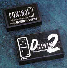
The mighty Domino packs an 80C52 processor with a full floating-point BASIC, 32-KB SRAM, 32-KB EEPROM, 12 parallel I/O bits, and a 2-channel 12-bit ADC in a 0.8-cubic-inch encapsulated package that consumes only 75 mW.
Domino is fully RS-232A, RS-422, and RS-485 compatible without extra components. Besides the two interrupts and three timers provided in the hardware, Domino is further enhanced by firmware which delivers an I2C bus, two PWM outputs, and direct period and frequency measurement.
Learn More...
PicStic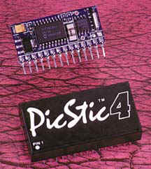
PicStic is a low-cost, industrial oriented controller on a 0.85-square-inch SIP (PicStics 1-3) or a DIP (PicStic4). Including options, PicStic incorporates digital inputs and outputs, analog inputs, real-time monitoring, power-input regulation, and serial communication (provided through software) in a single module. PicStics can be used independently or networked together.
The basic PicStic offers both compatibility and improved performance over the BASIC Stamp I. It comes in four versions: PS1, PS2, PS3, and PS4. The PS1, PS2, and PS3 are all pin-compatible with the Parallax BASIC Stamp I (BS1). The PicStic1 is a straight one-for-one programmable replacement for the BS1. |
Learn More...
Micro64/128
 The Micro64/128 is an industrial-oriented controller designed around the ATmega64/128 AVR microcontrollers. It incorporates 29 digital inputs/outputs, analog inputs, real-time clock, a serial boot loader and utilities to make it easier to use the peripherals. Micro64/128 comes in a single 1.5 -cubic-inch encapsulated package that consumes roughly 275 mW.
Learn More...
AnswerMan
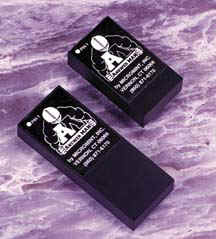 Answer MAN is a low-cost stand-alone or network-based data-acquisition and control module. As a small 0.8-cubic-inch standard 28-pin package, it can be used directly with a sensor or control device. It adds an analog/digital-to-serial data interface or supplements the control intelligence of sensors. Answer MAN provides the practical multipurpose interface between sensors and the computer.
Answer MAN communicates via serial ASCII protocol at speeds as high as 57.6 kbps. Answer MAN's simple Query or Set command language reduces costly programming. The tiny Answer MAN DIP packs together eight high-current parallel I/O lines, a 4-channel 8-bit ADC, a 2-channel 12-bit ADC, and a 2-channel 12-bit DAC (these are internal for the Answer MAN SR or external for the Answer MAN JR) along with a set of powerful firmware functions. These functions include keypad scanning, 4 x 20 LCD control, analog limit monitoring, data averaging, frequency and event counting, PWM output, and reading Dallas iButton serial numbers.
Learn More...
MicroBolt
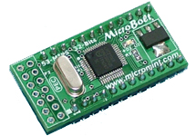 The MicroBolt is an industrial-oriented controller designed around NXP LPC2106 ARM7, 32-bit, 60 MHz, 53 Million Instructions Per Second microcontroller. It incorporates 19 digital inputs/outputs, a real-time clock, a serial boot loader, 128K Bytes of Flash and 64K Bytes of SRAM. MicroBolt is less than a cubic inch and consumes roughly 200 mW.
The MicroBolt utilizes a pair of UARTs to allow serial communication. With a 14.7456 MHz-system clock, the MicroBolt has the ability to communicate serially at baud rates up to 250Kbps. Very beneficial when time is a factor. SPI and I2C communications are also available.
Learn More...
The Micro64/128 is an industrial-oriented controller designed around the ATmega64/128 AVR microcontrollers. It incorporates 29 digital inputs/outputs, analog inputs, real-time clock, a serial boot loader and utilities to make it easier to use the peripherals. Micro64/128 comes in a single 1.5 -cubic-inch encapsulated package that consumes roughly 275 mW.
The Micro64/128 utilizes a pair of communication line drivers to allow several types of serial communication. RS-232A, RS-422, and RS-485 protocols are available for one of the two serial ports. With a 16MHz-system clock, the Micro64/Micro128 has the ability to communicate serially at baud rates up to 250Kbps. This becomes beneficial when time is a factor. SPI and I2C communications are also available.
In addition to the 8-channel-10-bit analog-to-digital converter supplied by the ATmega64/ATmega128, the Micro64/128 optionally offers a 2-channel-12-bit analog-to-digital converter.
The Micro64/128 has 29 bi-directional bit-programmable, digital I/O lines capable of sinking/sourcing 20mA.
Programs for the Micro64/128 can be created in assembly, BASIC or C programming languages.
Data Sheet
| Data Sheets | PDF (full) |
|
| Micro64/128 |
|
Ordering Information
|
Part Number |
Description |
Price |
|
| Micro64 | 29 digital I/O lines, 62k program space, 32k SRAM, 2k EEPROM, Real-Time Clock/Calendar, Serial Bootloader and Utilities |
$119
|
|
| Micro64A | 29 digital I/O lines, 12-bit ADC, 62k program space, 32k SRAM, 2k EEPROM, Real-Time Clock/Calendar, Serial Bootloader and Utilities |
$149
|
|
| Micro128 | 29 digital I/O lines, 126k program space, 32k SRAM, 4k EEPROM, Real-Time Clock/Calendar, Serial Bootloader and Utilities |
$139
|
|
| Micro128A | 29 digital I/O lines, 12-bit ADC, 126k program space, 32k SRAM, 4k EEPROM, Real-Time Clock/Calendar, Serial Bootloader and Utilities |
$169
|
|
Getting Started Files
| File Name |
Description
|
PDF
|
| Getting Started |
|
|
| Getting Started Project Files |
|
|
|
Micro64/128 Windows Boot Loader Software |
|
|
Application Notes
CodeVisionAVR C Compiler
|
Application
Note |
Description
|
PDF
Write-up |
CodeVision AVR Project Files
|
|
AN700
|
Using the RS485/RS422/RS232A Serial Port (USART1)
|
|
|
|
AN701
|
How to add additional Digital I/O using the I2C bus.
|
|
|
|
AN702
|
How to access the Optional 12-bit ADC
|
|
|
|
AN703
|
Demonstrates how to read and write to the 32k SRAM
|
|
|
|
AN704
|
How to read and write the to the I2C Real Time Clock Calendar
|
|
|
BASCOM-AVR Basic Compiler
|
Application
Note |
Description
|
PDF
Write-up |
BASCOM
AVR Project Files |
|
AN750
|
Using the RS485/RS422/RS232A Serial Port (USART1)
|
|
|
|
AN751
|
How to add additional Digital I/O using the I2C bus.
|
|
|
|
AN752
|
How to access the Optional 12-bit ADC
|
|
|
|
AN753
|
Demonstrates how to read and write to the 32k SRAM
|
|
|
|
AN754
|
How to read and write the to the I2C Real Time Clock Calendar
|
|
|
|
AN755
|
Demonstrates how to connect and write to an LCD over the I2C bus.
|
|
The mighty Domino packs an 80C52 processor with a full floating-point BASIC, 32-KB SRAM, 32-KB EEPROM, 12 parallel I/O bits, and a 2-channel 12-bit ADC in a 0.8-cubic-inch encapsulated package that consumes only 75 mW.
Domino is fully RS-232A, RS-422, and RS-485 compatible without extra components. Besides the two interrupts and three timers provided in the hardware, Domino is further enhanced by firmware which delivers an I2C bus, two PWM outputs, and direct period and frequency measurement.
Domino 2 has all the features of a Domino 1 plus an I/O coprocessor which adds 16 more bits of high-current parallel I/O, a hardware clock/calendar, wide-range power operation, and a hardware PWM output.
Dominos can be programmed directly from a serial terminal without special development tools. They can be programmed in either BASIC, a mixture of BASIC and assembly language, or mostly assembly language with just an initial BASIC CALL statement. Programs are initially developed in RAM and then transferred to the EEPROM for autostarting and permanent storage.
| Domino 1 | Domino 2 | |
| Datasheets |
|
|
Development Board
 The Domino 1 and Domino 2 Development Board takes the Domino 1 and Domino 2 I/O pins and expands them out to solder pads and headers for ease of connection when developing. It also connects the UART to RS-232 drivers or directly to screw terminals for RS-422 or RS-485 communication. The RS-232 driver is connected to a DB9 connector. This board also includes a prototyping area so the user can add on external circuitry. There is an onboard voltage regulator for powering the Domino 1 and Domino 2 and additional circuitry. The Domino 1/1A/2/2A development system comes complete with a Domino 1, Domino 1A, Domino 2, or Domino 2A, a Development Board, power supply, Domino Utilities, Host 52 and BASIC 52
The MicroBolt is an industrial-oriented controller designed around NXP LPC2106 ARM7, 32-bit, 60 MHz, 53 Million Instructions Per Second microcontroller. It incorporates 19 digital inputs/outputs, a real-time clock, a serial boot loader, 128K Bytes of Flash and 64K Bytes of SRAM. MicroBolt is less than a cubic inch and consumes roughly 200 mW.
The MicroBolt utilizes a pair of UARTs to allow serial communication. With a 14.7456 MHz-system clock, the MicroBolt has the ability to communicate serially at baud rates up to 250Kbps. Very beneficial when time is a factor. SPI and I2C communications are also available.
The MicroBolt has 19 bi-directional bit-programmable, digital I/O lines capable of sinking/sourcing 4mA. Other peripheral features include a 32-bit PWM, a programmable watchdog timer, two 32-bit timers and an optional JTAG debugger connector.
Programs for the MicroBolt can be created in assembly or C programming languages. The MicroBolt is pin compatible with the Parallax Inc's BASIC STAMP.
Data Sheet:
|
Data Sheet
|
PDF (full) |
| MicroBolt |
|
|
Part Number |
Description |
Price |
|
| MicroBolt | 19 Digital I/O, 128k program space. 64k SRAM |
$99
|
|
 The MicroBolt Development Board takes the MicroBolt I/O pins and expands them out to solder pads and headers for ease of connection when developing. It also connects UART0 and UART1 via jumpers to RS-232 drivers. The RS-232 drivers are connected to two DB9 connectors. UART1 can also be connected to a RS-485 driver for networking. The MicroBolt Development board provides connections to a LCD, SPI 12-bit 2 Channel ADC, LEDs, and an I2C EEPROM. This board also includes a prototyping area so the user can add on external circuitry. There is an onboard voltage regulator for powering the MicroBolt and additional circuitry. The MicroBolt development system comes complete with a MicroBolt, a MicroBolt Development Board, and a power supply.
 |
Part Number |
Description |
Price |
|
| MicroBolt Dev. Brd. | MicroBolt Development Board, and a power supply |
$89
|
|
PicStic 1-4
PicStic is a low-cost, industrial oriented controller on a 0.85-square-inch SIP (PicStics 1-3) or a DIP (PicStic4). Including options, PicStic incorporates digital inputs and outputs, analog inputs, real-time monitoring, power-input regulation, and serial communication (provided through software) in a single module. PicStics can be used independently or networked together.
The basic PicStic offers both compatibility and improved performance over the BASIC Stamp I. It comes in four versions: PS1, PS2, PS3, and PS4. The PS1, PS2, and PS3 are all pin-compatible with the Parallax BASIC Stamp I (BS1). The PicStic1 is a straight one-for-one programmable replacement for the BS1.
The PicStic2 has all the features of the PicStic1 plus a real-time clock/calendar that keeps time in terms of the year, month, day of the month, day of the week, hour, minute, and seconds. The clock always runs while the PicStic2 is powered. An optional 3-V lithium battery maintains the clock when power is off. The battery, which is approximately 0.6 inches in diameter, can be mounted on the front or back of the PicStic2.
The PicStic3 has all the features of the PicStic1 plus a 2-channel, 12-bit ADC. The compiler contains library routines for reading the ADC and real-time clock.
PicStic4 consists of a user-programmable controller, similar in most respects to our original PicStic1, enhanced with an intelligent I/O coprocessor. The coprocessor provides extended data memory, automatically reads and sets 12-bit analog I/O, reads or sets the real-time clock, and supports up to 19 bits of parallel I/O. Beyond the physical attributes, the coprocessor also provides numerous processing and data management functions which can be accessed from the controller side.
Complicated program tasks like scanning keypads, driving an LCD display, recording Vmin, Vpeak, and Vavg analog readings, reading and setting the real-time clock, recording important data in extended nonvolatile memory, totaling events, reading frequency, generating a constant PWM output, or reading Dallas Semiconductor iButton serial numbers, are all provided as simple callable functions from the I/O coprocessor. PicStic4 is designed to provide the user with a cost-effective and easily programmable control device without requiring the user to eat up valuable controller-side programming space with all the low-level code typically necessary to perform useful monitoring and control activities.
While PicStics 1-3 are BASIC Stamp I pin-compatible, you can program all PicStics in more than BASIC. Unlike the customized hardware of the BASIC Stamp, PicStic uses a generic reprogrammable PIC16F84 processor and customized compiler. Additional features and improvements typically involve recompiling your program, not buying new hardware.
The single major advantage of the PicStic is that you get additional I/O lines and access to the four PIC16F84 interrupt sources when using assembly language (or an assembly-language call appended to PicBASIC or C). With an ADC, interrupts, and 10 I/O lines, the PS3 provides a powerful little controller for cost-conscious applications.
Using the PicBASIC compiler, PicStic 1 is 100% Stamp I compatible. As a bonus, it's also at least 15 times faster for the same crystal speed.
PicStics are now available with double the program space, double the data EEPROM space, and over three times the RAM space. The 2k version is available for the PicStic 1, 2, 3, and 4. Micromint's part number is PicStic 1-2k, PicStic 2-2k, PicStic 3-2k, PicStic 4P-2k, PicStic 4Q-2k and PicStic 4X-2k.
PicStic 5
The PicStic 5 is a low cost industrial-oriented controller designed around the PIC16F876. The PicStic 5 incorporates digital inputs, digital outputs, analog inputs, analog outputs, extended data memory, and serial communication all in a single 0.8-cubic-inch encapsulated module.
The PicStic 5 utilizes a pair of communication line drivers to allow several types of serial communication. RS-232A, RS-422, and RS-485 protocols are available with the PicStic 5. With an 8MHz-system clock, the PicStic 5 has the ability to communicate serially at baud rates up to 250Kbps. This becomes beneficial when time is a factor. SPI and I2C communications are also available. These buses are made accessible through pins 23-25. During I2C communication the SCL frequency can be set at 100KHz, 400KHz, or 1MHz. During SPI communications, bits can be clocked out at rates up to 2MHz. In SPI and I2C modes received data is double buffered allowing a second byte of data to be received before the first byte is processed.
Accompanying the 4-channels of 10-bit analog-to-digital converters supplied by the PIC16F876 processor, the PicStic 5 also offers 2-channels of 12-bit analog-to-digital conversion. The two 12-bit channels can be sampled at approximately 10K samples/sec. The four 10-bit ADC channels can be sampled at approximately 20K samples/sec. There are 2-channels of 12-bit digital-to-analog conversion included in the PicStic 5. These analog outputs have a range from 0-4.095V. Both channels are loaded simultaneously.
The PicStic 5 has 16 bi-directional bit-programmable, high-current I/O lines capable of sinking/sourcing 25mA.
The PicStic 5 can be programmed using a Micromint supported BASIC Compiler, straight assembly language, or a C compiler (not supported by Micromint Inc).
Datasheets
|
Data Sheets |
PDF (full) |
|
|
PicStic 1-3 |
|
|
|
PicStic 4 |
|
|
|
PicStic 5 |
|


