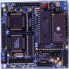
 One of Micromint's hottest-selling products for the past five years has been the RTC31/52 stackable controller. It has been a leading price/performance choice among our customers. With our new RTC320 and RTC52-Plus boards, we have expanded the value of that relationship even more.
Occupying the same small 3.5" x 3.5" RTC footprint and 5-V-only power, the RTC320 uses the new Dallas Semiconductor 80C320, which is 8031 code-compatible and 35 times faster. At 33 MHz, the RTC320 is an 8-MIPS controller! Along with the new powerful processor, the RTC320 board accommodates up to 192 KB of memory, 2 serial ports (RS-232 and RS-485), 24 bits of TTL parallel I/O, and a 2-channel 12-bit ADC. The RTC320 puts some real firepower under the abundant variety of RTC I/O expansion boards. Plugging in your favorite ICE or EPROM emulator is the easiest way to develop code. For the diehards who like to twiddle the bits directly, we have a ROM monitor specifically designed for the Dallas '320.
Click here to download the RTC-52PLUS and RTC-320 datasheets.
| Processor: | Dallas 80C320 | Clock speed: | 11/22/33 MHz | |
| Max Memory: | 192 KB | SRAM/EPROM: | 110 KB/64 KB | |
| Digital I/O: | 24 bits, PIA | Serial Ports: | 2 (RS-232 & RS-232/-485) | |
| ADC (sample rate): | 05 V, 2 chan., 12 bits (11.1k) | Timers: | 3 | |
| External Interrupts: | 2 | Real-time Clock: | Yes, SmartWatch socket (opt.) | |
| Size: | 3.5" x 3.5" | Power (fully loaded): | +5 V 33 MHz: 250 mA; 11 MHz: 125 mA |
|
| Dev. Software: | Optional | ROM Monitor: | Yes |
Call for Custom Configurations
This email address is being protected from spambots. You need JavaScript enabled to view it. or Call for Pricing
Errata
10/11/00
RTC-320/52P
There is an error on the PC board layout. It does not allow for the RTC-LCD to be interfaced with the board.
During the layout of the RTC-320/52P the *DS signal, which is used to write to the LCD on the RTC-LCD board, was over looked. To correct the problem a jumper wire must be soldered from pin 21 of U3 (P22CV10) to pin 22 of JP15. Version 1.3 of the PEEL chip (U3) supports the RTC-LCD logic.
This only effects customers that are stacking an RTC-LCD board on top of a RTC-320 or RTC-52 Plus.
When using an 8K RAM and 8K EPROM a jumper needs to be added to JP1. The jumper needs to be placed on pins 3 & 4 of the JP1 header.


