AN206
Serial PLIX
Date: 4/11/00
Background: The Serial Plix is an 18-pin CMOS chip, which provides an intelligent communication interface between a serial port and X-10 AC power-line control modules. Using our example software and a TW523 power-line adapter module, you'll see how easy it is to remotely control appliances and lights through the power lines.
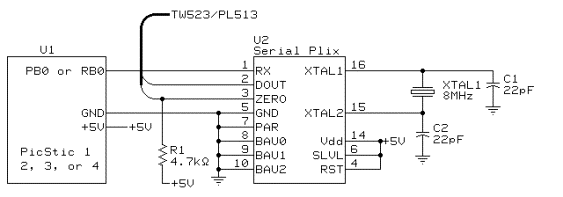
How it works: Serial Plix removes the burden of complex X-10 programming protocol from the designer by providing a simple serial interface. It takes care of the complex zero-crossing timing for sending and receiving X-10 commands so you don't have to. An otherwise simple embedded controller can now also feature X-10 power-line control by simply adding a Serial Plix chip to the design. The following schematic demonstrates all of the connections needed.

Program Listing:
‘ This program demonstrates how to control Serial
‘ Plix using a PicStic 1, 2, 3, and 4 with PicBasic.
Symbol SO = 0 ‘Define serial out pin
‘to be PB0 on the PicStic
Pause 1000 ‘Delay for voltage levels
‘to settle.
‘to turn on light
‘A16.
PAUSE 3000 ‘Delay to allow
‘serial plix to
‘complete it's
‘command.
Serout SO,N9600,("$DIMA1610") ‘Send the command
‘to dim light
‘A16.
PAUSE 10000 ‘Delay to allow
‘serial plix to
‘complete it's
‘command
Serout SO,N9600,("$BRTA1610") ‘Send the command
‘to brighten light
‘A16.
PAUSE 10000 ‘Delay to allow
‘serial plix to
‘complete it's
‘command
Serout SO,N9600,("$UONA1602") ‘Send the command
‘to turn off light
‘A16.
PAUSE 3000 ‘Delay to allow
‘serial plix to
‘complete it's
‘command
Goto Begin ‘Start the program
‘over.